Sunday 21 August 2011

Op amps


http://eduframe.net/andc
An op amp amplifies difference between the inverting V2 and no-inverting V1 inputs meaning that e.g picture V2 (non inverting) were higher than V1 then output would be Vcc- and if V1 were higher than V2 then output would be Vcc+.


NOTE:
A simple way to remember is when V2 is higher then that op amp will cause ground for the circuits (current flow from Vo to Vcc-)  while when V1 is higher then op amp will provide a voltage output ( current flow from Vcc+ to Vo)
                                 
IDEAL OP AMP:
When talking about "ideal op amp" it means that its produces the max it can with little voltage and the minimalist current possible also when connected to a frequency machine when changed without effect the ideal possible operation of op amps also heat factors as some component generate heat more than other but a ideal op amp wouldn't be bother by any heat factor and operate to its max ideally.                      

Non inverting op amps would allow voltage flow threw op amp output for the circuit to continue to ground. To calculate Vout would be:
www.wikipedia.com

Vout = Vin x (+1 (R1/R2))  If voltage was 12v, R1 AND 2 were 100Ohms then it would be                    Vout = 12 x (+1(100/100)) = 24 Vout


Inverting op amps which allows current flow to threw the inverting terminal (-) and flow out the non- inverting terminal for current will flow from Vout which will be positive and needing to be ground the op amp helps to achieve goal. When used in this application then this would be used for grounding circuits because of the negative feedback.With the 12v on the inverting terminal the Vout will be a negative number.
www.wikipedia.com


Vout = Vin x(Rin/Rf)         12Vin, Rin 100, Rf 100= Vout
Vout = 100/100 x 12= -12

This is one of many ways of using a op amp in application similar to relays, transistors etc, they take little amount of voltage/current and convert it into a more sufficient supply of voltage/current.




Thursday 18 August 2011

Fuel injector circuit.

The picture shows a fuel injector circuit, components are 2x LED, 4x resistors, 2x transistors and 2x power supply (12v, 5v).  Task is to calculate what resistors are need for this circuit to turn on without harming any components. A LED needs 1.8v and 20mA to turn on this means that when circuit is on, 1.8v will be used by the LED, therefore it is necessary to take 1.8 from 12 leaving 10.2v which makes voltage for calculations. now to find out the resistors needed so LED lights and flickers. R=V/A with this, resistor for circuit will be known.  R=10.2/0.02 (20mA) = R =510 Ohms. So 510 Ohms resistor is needed so that LED can turn on. Now the transistor, picture shows that its a NPN ( arrow pointing out ), with multimeter on diode check mode one of the three terminals will be common or will give readings when touching other terminals. Readings will be close but one will be slightly higher which will be the emitter and other as collector. Collector will need to be connected in series with LED as shown in picture. Now is to calculate what resistor is needed so that transistor doesn't start smoking (blown). now to calculate resistor, a transistor needs 0.6v to flow from base to emitter for it to turn on, which means 0.6 is subtracted from 5 = 4.4v just like before this is the voltage for calculations. now data sheet from www.fairchildsemi.com shows that in the saturated region the transistor will have IC=10mA IB=0.05mA with this I double IC and IB because I know that I need 20mA following through IC due to LED which then gives me IC=20mA IB=1mA. With this I can calculate resistor needed, R=V/A. R= 4.4/0.001= R =4400 Ohms and this is the resistor needed in series with base of the transistor. next task was to give a 50% buffer so I doubled it again as shown  R= 4.4V/0.002A= 2K2.

Next was to build circuit on lochmaster 3.0 

             This is the circuit on a breadboard.
Components list:

LED                                        1.8v / 20mA
R1,R2                                     12-1.8=10.2 / 0.02= 510 Ohms  R = V/A.
BC547 Transistor                    wwwfairchildsemi.com (Data sheet)
VCE
 (sat) Collector-Emitter Saturation Voltage    IC=10mA, IB=0.5mA   Max of 250mV
                                                                    IC=100mA, IB=5mA
R3,R4                                     5V- 0.6= 4.4/ 0.01= 4400 Ohms R= V/A
                                               50% = 4.4/ 0.02= 2200 Ohms. (Ohms law)

Power supply                          12V and 5V.         
                                                                 

REFLECTION:


When parallel circuit was built on breadboard and connected to power supply (12v, 5v), only one LED was lighting up and with a closer look, found that LED was backwards (positive and positive= off). after correcting it, I found that both LED were turning on but weren't blinking simulating pulsing of injector with was   the task. When looking closer, I had both bases of each transistors connected on the the same buzz bar showing that continuity needed to be broken and when done the frequency machine when changed was pulsing simulating the switching on/off of injectors which was the task.


Monday 15 August 2011

Diodes.

THEORY:


http://upload.wikimedia.org/wikipedia/commons/8/83/Diode_pinout_en_fr.svg
Diodes are a component in a electrical circuit that allows current to flow one way and not the other and is made of two semi-conductors which mean they are both semi insulators and conductors. When diode is connected in a circuit, the current flows through the diode and the rest of the circuit. This is known as  forward bias. This makes the electrons and holes in the diode push together towards the boundary layer which then makes the electrons easier to pull into the holes and allows current flow throughout the circuit. When diode is put in reverse in the circuit, this is called reverse bias meaning electrons
and holes move away from the boundary layer were it becomes harder to pull electrons into the holes. This would mean that voltage/current will stop at the diode and wont flow anymore throughout the circuit.


TEST:


When multimeter is connected to the diode in forward bias, the current/voltage will flow through the diode which will give a reading on the multimeter. When is reverse bias, the current/voltage flow will arrive at the diode and sit there resulting in current/voltage not flowing throughout circuit. When taking readings for current, the circuit needs to be broken for that reading. So when in forward bias the diode is being a conductor and in reverse bias it be becomes a insulator but when its a zener diode current/voltage can flow both ways . Zener diode allows current/voltage to flow in both direction, this is because zener diode are used mainly for high voltage circuit and bleeds off excess current/voltage so that components in the circuit are safe.

REFLECTION:


Diode are important for a number of reason but mainly because it is able to send current/voltage flow in one direction and not the other. If there were no diodes in a alternator, the A.C  that the alternator generates could not be rectified to D.C, this is possible due to the diode on the rectifier within the alternator.

Sunday 14 August 2011

Transistor.

THEORY:


http://upload.wikimedia.org/wikipedia/commons/

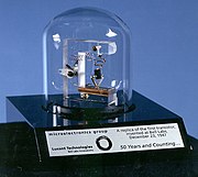
Transistors have been around since the 1920's, the difference is the material that its used. Just like back in the days, a transistor is used by taking a low amount of ampere to turn on (amplify) a high amount of ampere. Transistors come in 2 types NPN and PNP. One is base negatively on and other base positively. This is a three wire transistor that have a base, collector and emitter. The base is were a low amount of current travels from which then goes through to the emitter. When there's enough current flowing from the base to the emitter, it then opens the gate for the collector to join the base which then allows the high current to join with the low and pass through the emitter. This shows that low ampere is used to switch on high ampere. Transistors are a semiconductor like a diode and NPN or PNP   means N= free electrons P= holes N= free electrons. This shows how current/voltage would through a transistor which is just like a diode hence they say its 2 diode back to back. 

TEST:


http://curiosity.discovery.com/topic/computer-parts/electronics-parts-pictures1.htm
When determining which terminal is base, collector and emitter, a multimeter can be used with it on the diode test function. The base is the common to both collector and emitter. The collector will have a lower voltage running through than the emitter. When transistor is fully off, this is known as cut off region and when it fully on, this is known as the saturated region and when in between its known as active region. When in the active region, a high voltage drop will occur and if too high of a voltage drop it could cause heat, which can  build up and end up with the transistor burning out and may melt due to the heat. In the cut off region, there is no voltage/current through the base of the transistor at all therefore transistor is not operating. The saturated region is when the transistor is fully on and working and voltage drop is minimum.


REFLECTION:

Transistors have come along way from the 1920's. Modern man would not have had allot today like cellphones, computers if it werent for for the few men that produced the transistor. These components are important due to vehicles needing more than just 12v for some of its components. Like the old sayin goes big thing come in small packages.

Capacitors

THEORY:

Capacitor are used in a electrical circuit to store electrostatic charge. They are in some way like a battery but capacitors can not create new electrons that enter through the negative plate of the capacitor. A capacitor is made of two metal plates that are separated by a non-conducting insulator. There are many types of capacitors and all vary in how much it can hold/store. These components are used often for dampening voltage spikes and to time electronic . Capacitor store as much energy as is put into it e.g 12v battery, capacitor will store 12v until the battery is replaced with a wire which will then make a complete circuit will then cause the capacitor to discharge the electrostatic charge. If there were a bulb in the circuit, it would turn on but as the stored charge is used by the bulb it would make the bulb at first shine bright and then slowly get dimmer and finally go out.

TEST:


One test is to:

12v power supply, 1x 100ohm resistor, 1x 300uf capacitor, 1x N/O switch.

When circuit was made, it was in series which shows that voltage/ampere will flow through the circuit, through the resistor where it will regulate the voltage to the capacitor, were then voltage (electrostatic charge) is stored with switch parallel to capacitor and then circuit runs back to earth.

With switch on, the capacitor is able to get charged and store voltage. If a bulb was in the circuit, it would be very bright cause the power supply is good. As soon as switch is off, the bulb will remain on until all of the electrostatic charge is used making the bulb go dimmer and depending on which capacitor is used eventually going out.

A 300uf capacitor when fully charged takes about 90 seconds after switch/bridge wire is off,  before the voltage out of capacitor starts to even out which shows that the electrostatic charge is now low within the capacitor and at 180 second is now close to being empty.


REFLECTION:


If had a circuit and I needed a certain component in my circuit to be on after I have turned it off then I would put a capacitor in the circuit that would store the charge that I'd need for it. So capacitors are a important part of a circuit for its ability it store and disperse electrostatic charge.

Saturday 13 August 2011

Resistors.


http://www.williamson-labs.com/images/resistor-color-code-all.gif
THEORY:
A resistor is a component used in a electronic circuits to resist and regulate the    current/voltage so that other component in the circuit e.g L.E.D (0.02A, 1.8v) get voltage/current that would not exceed its max capability, if there were no resistor in the circuit and the power source is 5v, when circuit is turned on the voltage/current would flow through the L.E.D resulting with L.E.D being blown.

With a series circuit, if there are two resistors end to end that are the same value and power supply is 12v, each resistor would use up 6v but if one resistor is a higher resistance then it would use more of the available voltage and the rest would be used by the other resistor meaning voltage is proportional to the resistance in the circuit.
Ampere in this circuit (series) throughout is always the same from start to finish.

With a parallel circuit, if there are two resistors that were side by side and equal value, then like in a series voltage will need to be used up before returning to earth. When in parallel, amperes is proportional to the resistance meaning if a resistor was of a different value then which ever resistance is higher, that is the resistor that will use most of the ampere in the circuit showing that when resistors are in series resistance is high
and when in parallel, resistance will be low.

TEST:
These were a couple resistors that were tested:
R1 Colour bands:

Red(2), Violet(7), Yellow(4), gold(5% tolerance)
R2 Colour bands:
Brown(1), green(5), red(2), gold(5% tolerance)

Using the colour chart, R1, R2 is calculated as so:

2, 7, 0000, 5% = 270,000 ohms / 270 k.ohms with a tolerance of  +- 5%.(+ 275 k.ohms - 265k.ohms)

1, 5, 00, 5% = 1,500 ohms / 1.5 k.ohms with a tolerance of +- 5%.(+ 6.5 k.ohms /  - 3.5k.ohms)

With these calculations it was certain that R1 was able to handle up to 275,000 and to as low as 265,000 ohms and R2 was up to 6,500 ohms and as low as 0.03 ohms. This shows that these types of resistors are not made to an exact specification or value but have a of 5% either adding to decreasing it.

REFLECTIONS :

Resistors play an important part in a circuit because if there were none and the power supply is 12v, components that require a little amount of voltage or ampere would either heat up, may melt or just blow up. Resistors are a necessity for a safe operation of a circuit.